Procedure for Replacing the HET
Structure Azimuth Limit Switches
George Damm
1. Purpose
This procedure serves to document the work required to
replace the structure azimuth limit switches after an incident on
2. Scope
This document is limited to the physical replacement of the limit switch, reconnecting wires to the appropriate terminals and adjusting each of the 7 micro switches in the limit switch assembly so that each is triggered appropriately when the telescope is in the correct azimuth.
3. Applicable Documents
4. Required Equipment/Personnel
- soldering iron and solder
- 5/32 “ ball end allen tool
- small slotted screwdriver
- multi-meter, voltage and ohms
- 4 people required, 1 in the pintle bearing area to control structure azimuth with the pendant, 1 in the pintle bearing area to adjust the limit switches, 1 person to monitor and reinsert azimuth limit pin, 1 person to monitor the computer terminal in the control room to advise when certain limit positions have been reached.
5. Procedure
The procedure will consist of 1) removing the old limit switch, 2) unsoldering the old limit switch, 3) measuring the current set points of all 7 micro switches, 4) transferring the measured set points of the old limit switches to the new limit switch, 5) resoldering the new limit switch in place, 6) reattaching the new limit switch to the 80:1 step down gearing, 7) fine tuning the limit switch set points as a function of telescope azimuth. The 7 micro switches are monitored by the azimuth computer. Each of the 7 switches are actuated at a different telescope azimuth. The actuation of each provides an indication to the azimuth computer as to the absolute position of the telescope, independent of the encoders. Table 1 below shows the 7 different micro switches and how the azimuth computer responds to each.
Table 1. List of the 7 azimuth limits and the system response to each. Also description of the software limits
|
Limit Switch |
Function |
|
Cable Wrap (CW) |
Indicates which side of the cable wrap that the azimuth is located. Provides a CW/CCW indication on the computer monitor |
|
CW Velocity Limit (CWVL) |
Indicates a region of azimuth travel in which the manlift may interfere. Structure computer responds by limiting azimuth rotation speed. Currently disabled. |
|
CW Prelimit (CWPL) |
When activated computer responds by permitting motion away from CW limit, but not motion towards limit. |
|
CW Final Limit (CWL) |
When activated, computer responds by prohibiting further motion in either CW or CCW direction. Motors must be moved manually or limit switches jumpered |
|
CCW Velocity Limit (CCWVL) |
Indicates a region of azimuth travel in which the manlift may interfere. Structure computer responds by limiting azimuth rotation speed. Currently disabled. |
|
CCW Prelimit (CCWPL) |
When activated computer responds by permitting motion away from CCW limit, but not motion towards limit. |
|
CCW Final Limit (CCWL) |
When activated, computer responds by prohibiting further motion in either CW or CCW direction. Motors must be moved manually or limit switches jumpered |
|
CW Software Limit |
When activated, does not allow any computer controlled motion in the CW direction. Hand paddle can still move in CW direction |
|
CW Software Limit |
When activated, does not allow any computer controlled motion in the CCW direction. Hand paddle can still move in CCW direction |
5.1. Remove Old Limit Switch
On the night of
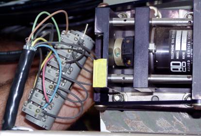
Figure 1. Photograph showing
the 7 pole rotary limit switch, next to the flexible coupling to the 80:1 gear
reducer. The other side (right, off edge
of photo) of the gear reducer has a 54 tooth gear that couples to a rotating
2160 tooth gear on the rotating part of the telescope structure.
In order to properly remove the limit switch, it must be unbolted from the front of the housing as shown in Figure 2. Three slotted screws in a 120° circle must be loosened. Each screw holds a metal tab that fits a slot in the front of the limit switch assembly. As the screws are loosened, the metal tabs can be swung clear of the limit switch slot. The
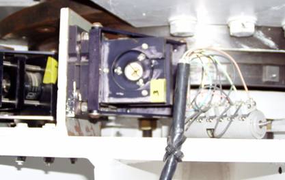
Figure 2. Photograph of the face of the flexible coupler that accept the rotary limit switch.
shaft of the limit switch must be loosened from the flexible coupling. The allen head
screw seen on the copper ring of the flexible couple in Figure 1 above must be loosened to permit the shaft to be pulled free.
5.2. Desolder Old Limit Switch
Once removed, the old limit switch must be desoldered from its connections. Schematically, the limits switch is shown in Figure 3 below. The limit switch assembly is manufactured by Precision Mechanisms Corporation, model #CS-402-7. When soldering or desoldering wires to the terminals, the manufacturer states that the soldering iron should be set to 550°F and held to the solder terminal for not more than 10 seconds.
Figure 3. Schematic of the limit switch connection. The azimuth data gearbox is the limit switch located at the pintle bearing. The power drive unit is located with the azimuth control system in the Upper Electrical Room.
Figure 4 is a diagram of the location of the 7 individual limit switches within the overall switch mechanism. The color code of the wire is also shown. The black wires are distinguished from one another a numbering scheme seen in the figure.
Figure 4. Diagram showing
the location of the individual limit switches and the color code of the wiring
within the limit switch assembly.
5.3. Measure the location of old switch actuation
In order to simplify the adjustment of the new limit switch, it is advisable to record the positions of the 7 current (old) limit switches. These positions can then be transferred to the new set of limit switches. The back of the rotary switch assembly, away from the shaft contains a slotted shaft that rotates within a set of markings each set at 30° intervals. Using a fine slotted screw driver one is able to rotate the shaft to an accuracy of 15° degrees, about midway between the set of 30° marks.
Each of the 7 individual micro switches must be measured
independently. An ohm meter, preferably
with an audible short indicator, is connected between the common and the N.C.
connection of the switch to be measured.
Rotating the slotted shaft clockwise, the shaft position is noted for
those points at which the normally closed contacts open and then close. The position is noted to within 15°. Care should be taken to use the correct
(marked with red) end of the slotted shaft to indicate the angular position. This procedure is repeated for all 7 micro
switches. The positions recorded for the
incident of
Table 2. Angular (hours of the clock) location of the on and off switch points for each of the 7 azimuth limit switches.
|
Limit |
On (Open)Location |
Off (Closed)Location |
|
CW |
|
|
|
CWVL |
|
|
|
CWPL |
|
|
|
CWL |
|
|
|
CCWVL |
|
|
|
CCWPL |
|
|
|
CCWL |
|
|
5.4. Adjust new limit switch to match old limit switch location
The position of the old limit switches recorded in Table 2
must be transferred to the new limit switch.
Two adjustment screws, A and B, are adjustable for each limit
switch. Next to each adjustment screw is
a set screw to fix the position of each.
Each adjustment screw is labeled on the end cap of the limit switch
assembly on the end opposite the shaft.
Precision Mechanisms Corporation publishes a set of instructions on the
adjustments. From our experiences on
Table 3. List of adjustment
screws that control the On and Off transitions for the 7 Azimuth limit switches
when shaft is turned clockwise.
|
Limit |
Adjustment Screw for On Control |
Adjustment Screw for Off Control |
|
CW |
A |
B |
|
CWVL |
B |
A |
|
CWPL |
B |
A |
|
CWL |
B |
A |
|
CCWVL |
B |
A |
|
CCWPL |
B |
A |
|
CCWL |
B |
A |
5.5. Resolder new limit Switch
Using the diagrams shown in Figure 4, resolder the wires to
the new limit switch. Follow the
manufacturer’s recommendation, using a 550°F soldering iron, not holding the
tip to the terminal for more than 10 seconds.
5.6. Reattach new limit switch
The procedure for attaching the new limit switch is the
opposite of that for the removal.
Referring to Figure 2, place the shaft of the limit switch assembly into
the flexible coupling. One by one,
reinsert the slotted screws on the face of the mount. After each is inserted, turn the metal tab on
the screw so that it engages the slot on the front edge of the limit switch
assembly. After all screws are inserted
and the metal tab on each engages the limit switch, tighten all 3 screws. Finally, tighten the hex head screw to firmly
couple the limit switch shaft to the flexible coupling.
5.7. Fine Tune the new Limit switch location
The limit switch is coupled to the structure azimuth through gearing. The structure azimuth has a 2160 toothed gear that rotates with the structure. A 54 tooth gear interfaces to the azimuth gear for a 40:1 amplification of rotation. An 80:1 gear reducer transfers the motion of the 54 tooth gear to the shaft of the limit switch assembly. The entire gear train reduces the azimuth/limit switch rotation by a 2:1 ratio. For every 360° of rotation of the structure, the rotary limit switch turns 180°. Since we are only able to identify 15° of motion when initially setting the limit switch positions, there is a 30° uncertainty for the switch actuation. This is the reason for adjusting the limit switches once they are engaged with the structure.
We did not have the original azimuth positions for each of the limit switches so we decided upon the most logical settings. 1) The azimuth position at which the lanyard was pulled was measured for both CW and CCW rotation. This represents the extreme physical limit for rotation in azimuth. Engaging these switches trips the breaker that powers the azimuth rotation motors. 2) We know the CW and CCW software limits based on a warning provided by the computer as the structure rotates. 3) The angular difference between the physical end of travel and the software limits was divided into thirds. The Final limit for both CW and CCW travel is placed one third of this angle away for the physical end of travel (lanyard pull). The Prelimit for both CW and CCW travel is placed two thirds of this angle away from the physical end of travel. . 4) The Cable Wrap (CW) switch should engage at 0° to indicate which side of rotation that the cable wrap was located. 5) Since the both CW and CCW velocity limit switches were not used, the azimuth for both of these switches was moved beyond the final limit azimuth. In order to properly set each limit switch, a multi-meter was placed across the common and N.C. contacts. When not asserted, the voltage across these two points would read 0. When asserted, this limit switch would open and the multi-meter would read 24 V. The adjustment technique suggested by the limit switch manufacturer was used. Table 3 was also used to quickly determine which adjustment screw to use.
Based on this logic, the telescope was moved in azimuth to
the correct position and the appropriate limit switch adjusted. Once each was adjusted, the azimuth was moved
away from the limit in question and then moved back to accurately record the
actual azimuth at which each limit was actuated. Once the Prelimit was actuated, it was
necessary to jumper the appropriate CW or CCW limit switch in order to permit
motion beyond this point enabling us to actuate the CW and CCW final limit
switches. Once this switch was actuated,
it also required jumpering in order to move off these limits. Table 4 below shows the desired and actual
azimuth positions for each of the limits switches. Figure 5 Below shows this same information
diagrammatically.
Table 4. Calculated and
measured azimuth positions for each of the limit switches. Also shown are the software limits.
|
Limit |
Calculated Azimuth |
Measured Azimuth |
|
CW |
0° |
6.7° CW |
|
Software CWL |
N/A |
180° CW |
|
CWPL |
185° CW |
183.9° CW |
|
CWL |
190° CW |
189.9° CW |
|
CWVL |
>190° CW |
164° CW |
|
Software CCWL |
N/A |
90° CCW |
|
CCWPL |
81° CCW |
82.1° CCW |
|
CCWL |
73° CCW |
72.9° CCW |
|
CCWVL |
<73° CCW |
<73° CCW |
Figure 5. Schematic view
showing full 490° of rotation (CW to CCW lanyard) and the location of the
azimuth limits as adjusted. All angles
are given in the structure coordinate system.