Introduction
The Segment Alignment Maintenance System (Sams) at the Hobby Eberly Telescope (Het) contains 480 sensors that measure gap, shear, and temperature values once per second when Sams is running. Sams calculates target sensor values for each of the 480 sensors every seconds. The output from Sams consists of 273 tip, tilt, and piston values, generated every 35 seconds or so when Sams in controlling the Segement Control System (Scs). In addition, a summary file containing average values and overall system state with a total of nine values, also generated once per second. This is a huge data set to analyze by hand. The Sams Analysis Software (Sas) package provides tools written in Python to easily consolidate multiple log files so that they can be used with visualization tools such as Matplotlib or PyQt.
Various names for this packages have been suggested
- Sams Initial Log Look and analYsis (Silly)
- SAMS Correlative Log Understanding-Booster (Sams Club)
- Sams Analysis Tools and Objects Required for Inspection (Satori)
- Sams Application Resource for Comprehensive Analytic Synthesis and Measurement (Sarcasm)
- Sams Log Analysis Program (Slap)
- Sams Analysis Tool and Inquiry ResourcE (Satire)
- Sams Log Analysis Program/Platform (Slapp)
but right now its just called the Sams Analysis Software (SAS). Suggestions and votes are appreciated.
Sams Nomenclature
Segment Numbering Scheme
There are a number of different segment numbering scheme with in the primary mirror array. These various scheme were developed at different times and for different reasons.
- M number (Mnn) - developed by Frank Ray, an astronomer at UT, this was the first numbing scheme used. It numbers the segment starting from the lower left and ending at the upper right. In the first vision for the mirrors the six corner segments were not included. When they are added later in the program these segment continued the scheme starting sequentially starting from the bottom corner and working counter-clockwise around the array. M number is designated by ‘Mnn’ where ‘nn’ runs from 01 to 91 and includes the leading zero.
- CR number (cc:rr) - developed by Phillip McQueen, an astronomer at Het, this scheme designates segments by the column and row of the segment. This scheme makes it easier to visualize where the segment is when discussing segments in conversation or written documents. Note that this is not a rectilinear coordinate system. Column:Row is designated with the notation cc:rr where ‘cc’ is the column number which may have a leading zero and ‘rr’ is the row number with or without a leading zero. For example, segment 43, in the center of the array may designated as ‘6:6’, ‘06:6’, or ‘06:06’
- S number (Snn) - developed by BlueLine Engineering during the installation of the Sams system, this system number the segment in a spiral patter start at the center segment. Therefore the center segment M43 == 6:06 == S01. The S number is designated like the M number by ‘Snn’ where ‘nn’ runs from 01-91 and includes the leading zero.
- Sensor numbers (seg-n) - each segment has six sensors except for edge mirrors which will only have sensors where there are neighboring segments. The sensors are designated 1 to 6. When referring to a sensor the sensor number is prefixed by the segment number (in which ever scheme your like) followed by a dash and the sensor number. For example, sensor 2, on the center segment, would be designated as M43-2, S01-2, or 6:06-6.
The SAS software will accept any of these forms of segment-sensor designation whenever a segment or a segment-sensor is required.
Segment and Sensor Location
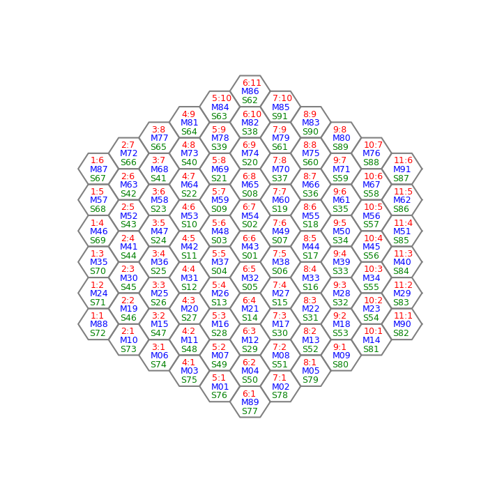
The location of the segments in the array and their various designations. The view is looking down on the segment.

The sensor locations on a segment. Sensors are designated 1-6 and the view is looking down on the segment.
Log Files
There are a number of log files that Sams records. The files are generally named as samsYYYYmmddHHMM.suffix where suffix will be one of .deg, .ebi, .gap, .sen, .tsn, .ttp, .sum, .log, .ref, or .dat.
The following files contain 480 sensors values. Rows in the files are constructed of a date/time of the form YYYYmmddHHMMSS followed by either 480 data values. The fields are tab separated. Suffixes and their data are:
- .deg – temperature files, each row contains a date/time and the temperature of the individual sensor in degrees C. Contains 481 columns and Sams segment-sensor order.
- .ebi – ebias file, these are filed with zeros and are not used in general trouble shooting.
- .gap – gap file, each row contains a date/time and the gap (in/out) values of the 480 sensors in microns. The sensors can measure accurately to 1500 microns but I don’t know where the upper limit is.
- .sen – shear file, each row contains a date/time and the shear (up/down) value of the 480 sensors in microns. Data values will range from -384 to +384 with +/-384 designating a saturated value. Contains 481 columns in Sams segment-sensor order.
- .tsn – target sensor files, each row contain a date/time and the residual square error in nanometers for each sensor. Contains 481 columns in Sams segment-sensor order.
The following file contains 273 segment values. Rows in the files are constructed of a date/time of the form YYYYmmddHHMMSS The fields are tab separated.
- .ttp – tip/tilt/piston files, each row contains a date/time and the tip/tilt/piston values for the individual segments. Contains 274 columen index by M number order. That is, the columns will be: data/time M01 tip, M01 tilt, M01 piston, M02 tip, ..., M91 piston. These data are generate every 35-36 seconds when Sams is sending commands to SCS
The following files contain the state or other information about the Sams server itself. Rows in the files are constructed of a date/time of the form YYYYmmddHHMMSS followed by either 9 data values. The fields are tab separated.
- .sum – summary files, contain the state of the system at the given time. It contains 10 columns. The columns are:
- date/time of the form YYYYmmddHHMM
- RSE in nanometers
- unknown
- Target RSE in nanometers
- FWHM of the tip/tilt errors in arc-seconds
- Average gap in microns
- Pending GROC (Global Radius of Curvature) correction in microns
- Total GROC in microns
- Average temperature of the sensors in degrees C
- unknown
- .log – this file recorded the commands that are send to the Sams server. The files reside in /home/jove/guider/SAMS/7.1/LOG with the same file name convention as the other files, i.e. samsYYYYmmddhhmm.log. However the time format inside the file is different from the other log files. In this case the time format is YYYY:mm:dd:hh:mm:ss. Interesting commands that can be found are
- getsamsdata
- getttp
- ttpdone nnnnn n
- setrefpos /home/jove/guider/SAMS/7.1/REF/sams20170923083048+18.2.ref
- setrefpos done
- removesen 85 3
- installsen 85 3
- removeseg 87
- installseg 87
- setmode Operate
- setmode Standby
- setcaldata /home/jove/guider/SAMS/7.1/CAL/COEF/coefficients_current
- .ref – reference files, contained the reference position for all the sensors. The files are located in /home/jove/guider/SAMS/7.1/REF. The naming convention is samsYYYYmmddHHMMSS[+|-]tt.t.ref, where tt.t is the temperature in degrees celcius with a plus/minus sign.
- .dat – The .dat file reside in /home/jove/guider/SAMS/7.1/MIRRORINFO. The naming convention is MirrorInfoYYYYmmddHHMM.dat. These files contain 10 data points consisting of zeros and ones for each of the 91 segments using Mnum for the indexing. It is unclear what the data mean. The source code will have to be searched to find out.