|
|
| Home | Problem Reports | Operations Schedule | Weather | Data Archive |
|
|
Grant M. Hill Sept 21, 1999 Introduction Procedure Analysis and Conclusions Introduction It is assumed the reader is already familiar with the burst/anti-burst alignment technique and its use of hysteresis corrections. Unless explicitly stated, all angular measurements are in mirror coordinates. We have known for some time that hysteresis in the HET mirror mounts depends on the size of the move. In the current 3-ring burst/anti-burst stacking, for example, the measured hysteresis corrections are very small for the innermost (5 arcsecond) ring. The corrections for the 10 and 15 arcsecond rings are significant though. During the summer of 1999, very small single ring patterns with a throw of only 2 or 3 arcseconds were designed to facilitate work with CCAS. Stacks with these patterns yielded EE(50) and EE(80) values only slightly bigger than for a single mirror, using no hysteresis corrections. Unfortunately, with such tight patterns, one can only stack a half dozen mirrors at a time. Past bench tests of the mirror mounts by François Piché and others implied that hysteresis was minimal out to some distance (determined in actuator steps) after which it increased with distance moved. Translated into arcseconds, the number of actuator steps roughly equaled 10 arcseconds.
It was thus inferred that some improvement in image quality might
be obtained by shrinking the 3-ring burst/anti-burst patterns slightly.
The middle ring, at 10 arcseconds, if shrunk even slightly might be
brought inside a 'break-point' such that hysteresis is greatly reduced
for the mirrors in that ring. Additionally, hysteresis in the outer
ring mirrors might be reduced by decreasing the throw distance for
these mirrors.
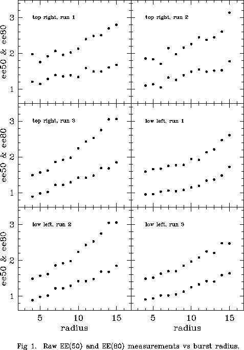
Twelve mirrors (13 counting mirror 43) were stacked at a time using a single ring pattern
and the burst/anti-burst technique. No hysteresis corrections were used.
The stacks were performed with a variety of ring radii and EE(50) and EE(80)
measured after each stack. The radius was varied in single arcsecond
steps between 4 and 15 arcseconds. Two different groups of mirrors
were used, corresponding roughly to high on the right side of of
the mirror and low on the left side. Each group was stacked 3 times
at each radius. Figure 1 presents the raw EE(50) and EE(80)
measurements for the six runs.
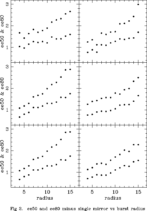
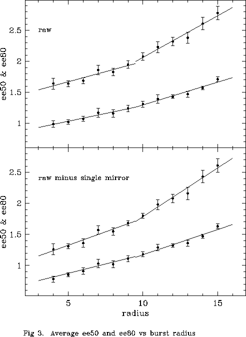
In an effort to reduce noise, the measurements displayed in Figures 1 and 2 were averaged. These averages are shown in the upper and lower panels respectively of Figure 3. The error bars are the standard deviation about each mean point. Both EE(50) and EE(80) increase with throw radius. Adequate fits seem to be provided by two straight line segments with the break around 9 or 10 arcseconds. A single curve can not be eliminated though. EE(80) seems to be the more sensitive indicator. It is assumed that the increase of EE(50) and EE(80) with throw radius is a result of hysteresis increasing with move size. The presence of an increase in the slope of the variation around 9 or 10 arcseconds agrees with expectations based on the past bench tests mentioned above. It was decided as a result of these results to shrink the ring radii from 5, 10, and 15 arcseconds to 5, 9, and 13 arcseconds. On average, hysteresis corrections did not diminish much (only a few percent). However, there are now fewer very large corrections. For the outer ring maximum corrections declined from about 1.0 arcsecond to about 0.6 arcseconds. For the middle ring the maximum corrections declined from about 0.6 to 0.4 arcseconds.
As of this writing, average EE(50) and EE(80) are
1.07 and 1.80 in sky coordinates.
Prior to adjusting the pattern size, they were 1.23 and 2.09 respectively.
Top of Page Return to Technical Reports List |
Created: see
report date above Send comments to: webmaster@het.as.utexas.edu |