High-Resolution Spectrograph
 |
|
|
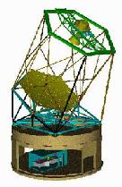
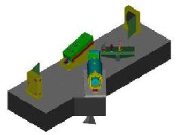
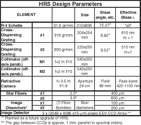
The HRS is a single channel adaptation of the ESO UVES spectrometer as described by Tull. ("High-Resolution Fiber-Coupled Spectrograph of the Hobby-Eberly Telescope," SPIE Conf. 3355-21, Kona, March 1998). It uses an R-4 echelle mosaic with cross-dispersing gratings to separate spectral orders. An all-refracting camera images onto a mosaic of two thinned and anti-reflection coated 2K x 4K CCDs with 15 micron pixels. The CCDs are abutted along their 4K side with a ~72 pixel dead space between them. This dead space is approximately parallel to the spectral orders. Resolving powers of R ~ 15,000; 30,000; 60,000; and 120,000 will be available by means of four effective slit widths. Spectral coverage is 420 - 1100 nm. The HRS will enter instrument commissioning in March 2001.
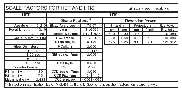
Overall Description The HET HRS spectral resolving power ranges from R = 15,000 - 120,000, with full spectral coverage on a mosaic of two Marconi CCDs, each with 2048 x 4100 x 15 µm pixels. The HRS is a "white pupil" spectrograph using the 2-mirror collimator system pioneered by Hans Dekker and Bernard Delabre at ESO: Mirror M1, the main collimator, is an off-axis paraboloid used in auto-collimation, with the entrance slit at its focus. After the dispersed light is reflected from M1 the beam comes to an intermediate focus, offset from the slit by an amount controlled by the off-plane tilt of the echelle, which is 0.8ş. Mirror M2 has identical figure and focal length but is farther off-axis by a distance equal to the separation of slit and intermediate focus; it serves to
The "R-4" Echelle The Echelle is a mosaic of two R-3.75 gratings replicated on a single blank at the Richardson Gratings Lab of Spectronic Instruments Inc.
Cross Dispersing Gratings
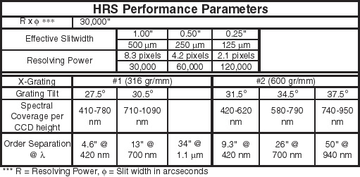
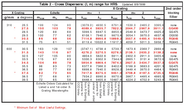
Setups For spectral stability we chose to allow the echelle and gratings tilts to be varied only in fixed steps. Both the echelle and the cross-disperser grating tilts are selectable in 1ş intervals. For the echelle, the exact interval is not yet determined, however for ease of alignment we are currently considering settings that would place the red He-Ne laser line in the center of the CCD for two setups. These settings will translate the blaze maximum 23.5 mm and +15.3 mm, corresponding typically to a wavelength shift of half the free spectral range. For most applications no shift should be needed unless, e.g., a spectral feature of interest falls on a blemish on the CCD. This shift also allows spectral observations in the near-infrared, where the free spectral range is slightly greater than the width of the CCD. This will occur for wavelengths greater than 910 nm. For the cross-disperser gratings, the 1ş tilt intervals are not adjustable. Table 2 below lists the relevant data for the available tilt settings and the Schott filter that should be used for each setting for blocking the second-order spectra. For convenience, Columns 9-11 list the second-order spectra. These are to be blocked by the Schott filters listed in column 12.
See the HRS Configurations Check script to see if an HRS configuration is valid or not.