MOSOBS
Notes on MOSOBS
This tool allows the user to quickly compute the X offset (in
pixels) for a MOS setup. Additionally, with a pre image present,
it provides a quick verification that LRS has achieved the proper
position angle (PA) and that the mask alignment is good.
|
|
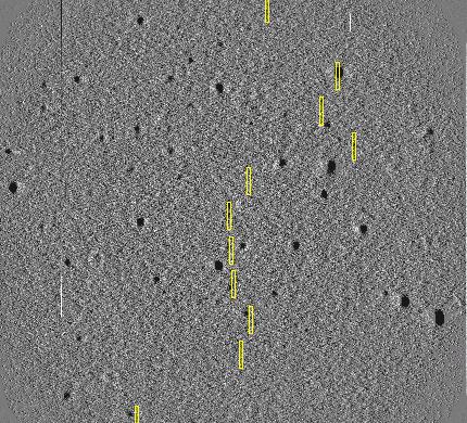
Figure 1: A full field view of an LRS MOS field with the slit positions
(mapped by MOSOBS) overplotted. A one-dimensional running median low-pass
filter has been subtracted from the original (20 sec) LRS pre-image to
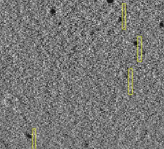
enhance faint sources across the entire field. In Figure 2 (below) we
show close-up views of the bottom and top MOS slits. The fact that the
slit targets switch sides in these two images indicates a PA (position
angle) error that occurred during the rho-offset phase of the mask
alignment process.
|
|

|
|
Figure 2: Bottom slits (LEFT) and top slits (RIGHT).
|
Further Developments
On Oct10,2004 (UT) we used MOSOBS to help align a mask. We
determined a rotation of 0.8 degrees was need, but the direction of
rotation was difficult to know. The next night I took a few
quick LRS images to determine this.
test1: from /data1/lrs/astronomer/20041011

Image of field for J1849+3024
rho1_west.fits    == image taken in west            RHO_OFFSET = 0
rho1_west+10.fits == rho changed by +10 degrees     RHO_OFFSET = 10

  =====> This +10 rho offset moves objects counter-clockwise


Image of field for J2346+0705
rho1_east.fits    == image taken in east            RHO_OFFSET = 0
rho1_east+15.fits == rho changed by +15 degrees     RHO_OFFSET = 10

  =====> This +15 rho offset moves objects counter-clockwise

SO, a positive rho_offset moves the field a counter-clockwise. This
is true wherever the telescope is pointed.
|
|
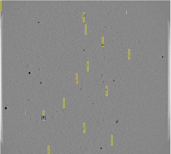
Figure 3: A well-aligned MOS field from Oct10,2004. The MOSOBS code
was used to very quickly derive the reference star offset. After
the first pre image was obtained it was determined that a 0.8 degree
change in the position angle was reuired to align the mask.
|
Some Rambling but Practical MOSOBS notes
To run MOSOBS

NOTE: renaming not absolutely necessary, but makes
      operation during setup much easier

1) Take mos image, imcopy it to name = slit.fits

2) Pull over the config file and name it cfg
   N.B. You must be on LRS to "see" these. You can copy it
        in the LRS ICE window before running "mos setup".
        The files are in /home/lrs/astronomer/ICE/MOS/
        sample file:
        /home/lrs/astronomer/ICE/MOS/M04-3-001.mod.cfg

3) Run MOSOBS and use a fake name for the pre image. Take
   results from the dX calculation and apply this offset
   directly to the X position of the setup star given in
   cfg file. Use this new corrected setup position in mkoffx4.

4) After the mkoffx4 is performed, take the test image.
   Copy it to file name = pre.fits.

5) Run MOSOBS and confirm that slits are placed on faint
   sources.

6) If sources are offset ina systematic way, then circle clearly
   visible targets with a red circle marker. MOSOBS will use these
   positions (relative to slits) to compute a position angle
   change and the predicted RHO_OFFS needed to effect that change.

   Be aware that you will have to perform the mkoffx4 step again
   after the RHO angle is used.
An example of a MOSOBS run
Below is a complete expample of a MOSOBS run (as of Aug2006). The
input images are slit.fits and pre.fits. The name of the MOS configuration
is cfg. User responses are denoted with red fonts.
Data are in (mcs):  ~sco/het_data/mosobs/S7

[sco@mcs S7]$ MOSOBS
Calling system to get time
system call complete

Enter name of slit image (lrs1000slit.fits): slit.fits

Enter name of pre image (lrs1000pre.fits): pre.fits

Enter name of slit config file: cfg

 Derive the best dX offset for the MOS setup. Recall this is
 the offset the you will add to the set-up star position
 listed in the finding chart. This new offset position is
 what is inserted into the mkoffx4 icex routine. Hence, when
 you run mkoffx4 and click on the set-up star, that star will
 be placed at the point on the mask that will align all of
 the slits with their targets.

Enter any key to continue:

# BESTDX:
Slit  image: slit.fits
Config file: cfg
Mean X offset values:
 slit     Xmos      Xconf       dX
  1      160.91    166.18     -5.27
  2      371.77    376.57     -4.80
  3      279.82    284.70     -4.88
  4      144.24    149.27     -5.03
  5      212.11    216.96     -4.85
  6      354.81    359.35     -4.54
  7      254.62    259.34     -4.72
  8      292.37    296.98     -4.61
  9      430.39    435.08     -4.69
 10      341.84    346.31     -4.47
 11      285.26    289.76     -4.50
 12      278.22    282.68     -4.46
 13        2.00     -1.00   -999.00   No slit

Mean dX offset     =    -4.736
Median dX offset   =    -4.709
Sigma of dX offset =     0.244
Add this offset to X position of setup star in config file.

RHO_OFFS from image header =   -22.19

Methods available to make the low-pass image:
 1) 2-D running boxcar filter (Slow)
 2) 1-D boxcar filter
 3) 1-D boxcar median
 4) 2-D (up to 30 term) surface map
Input index of method you want: 1
Enter linear radius of boxcar filter (12):  12

Writing FITS image: u.fits

=====================================
No ds9 window is open. I'll open one!
=====================================

Executing: ds9 -geometry 600x800 &

  ===================================================
  WAIT FOR THE DS9 WINDOW TO OPEN BEFORE YOU PROCEED.
  ===================================================


Enter any key to continue:
DS9 window tool called.

Enter any key to continue:

Enter any key to continue:

===========================================
Mark offset sources with red circle marker.
===========================================

Enter any key to continue:
Number of offset sources located by user =    2

 ================================
 Original RHO_OFFS      =  -22.19
 Suggested new RHO_OFFS =  -20.42
 ================================

Note: Important results summarized in "mosobs.results".
Back to OBSTOOLS Page