|
|
| Home | Problem Reports | Operations Schedule | Weather | Data Archive |
|
|
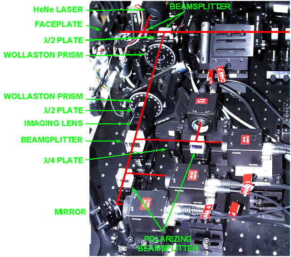
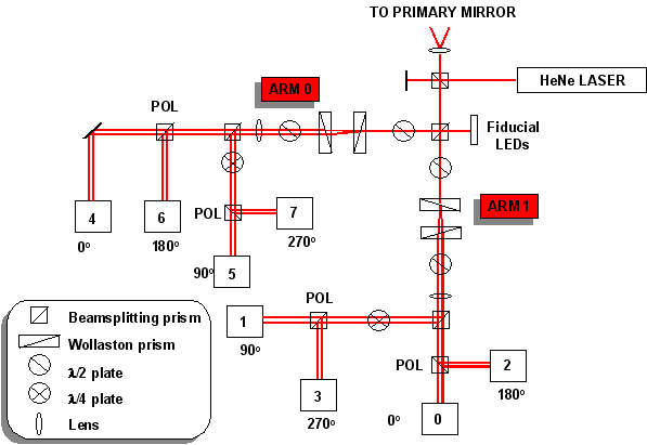
APPENDIX A APPENDIX B APPENDIX A Details of Optical Layout and Theory of Operation in Tip/Tilt Mode Section 3.1 of this report gives a description of the CCAS operation in tip/tilt measurement mode. Many details left out there are covered in this appendix. One important aspect not previously covered is the optical layout of the interferometer. One arm of the instrument is pictured in Figure A. HeNe laser light is sent out to the left through the indicated faceplate to the HET primary mirror. The beam expands, after being focused through a microscope objective just ahead of the faceplate, to fill the entire primary mirror. It reflects off of each mirror segment, comes back to a focus at the faceplate, is re-collimated via the same microscope objective, then is split into two beams traveling right to Arm 1 and down to Arm 0. Each of these beams travels through various prisms, polarizing beamsplitters, and waveplates, splitting into 4 paths and reaching 4 video cameras. A schematic of this layout is shown in Figure B.
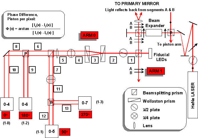
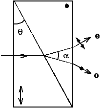
Top of Page We will now zoom in on Arm 0 and discuss what each optical element does to the light. A schematic for this is shown in Figure C. The numbers in boxes represent points throughout the beamtrain at which we will examine the state of the light. The HeNe laser is polarized and has a half wave plate on the front to rotate the beam such that it is linearly polarized at 45o. The light goes through a polarizing beamsplitter, which reflects the vertically polarized light (denoted as a dot into the paper) to a beam dump, and passes the horizontally polarized light. The transmitted light goes through a beam expander and exits with a diameter of approximately 1-inch. The light passing straight through the next beamsplitter hits a dump that is actually a shutter. When the shutter is open, the HeNe beam is sent back into the instrument for optical alignment. When the shutter is closed, this light is just absorbed. The light reflected by this beamsplitter (up on the diagram) goes through a microscope objective, focuses through a pinhole in the faceplate, and expands to fill the HET primary mirror. It is then reflected by each mirror segment back up to a focus at the faceplate and is re-collimated by the microscope objective. It has the same horizontal polarization that it had before going down to the primary. Light from two separate segments, A and B, is denoted as such in the figure. The beam actually forms a parallel image of the whole mirror array at this point. It passes back through the beamsplitter that sent it down to the primary and is split into two images at the next beamsplitting cube. The light traveling straight down goes to Arm 1 and light traveling to the left goes to Arm 0. At position 1, we have an image of the entire primary mirror array that is horizontally polarized. This goes through a half wave plate with its optical axis adjusted such that the image at position 2 is linearly polarized at 45o. The next element is a Wollaston prism, consisting of two wedges cemented together. The optic axis of the material is perpendicular in the two halves. This has the effect of deviating the ordinary and extraordinary rays away from each other at an angle, α, given by where
The second Wollaston prism is oriented opposite to the first, which has the effect of reversing the angular deviation so that the emerging beams are parallel. The spacing between the two prisms is such that the emerging images are separated, or sheared, by a distance corresponding to one mirror segment of the array. The polarization state after the second Wollaston prism at position 4 is shown in Figure F. The next component is a half wave plate that flips the polarizations by 180o. The lens after the waveplate is the final imaging element for the upcoming cameras.
The beam is split into two by the next beamsplitting cube. For the straight through path (left on the layout), a polarizing beamsplitter transmits half of the beam and reflects the other half while adding a 180o phase shift to its polarization. The polarization state for positions 5, 6, 7, and 8 is shown in Figure G. The polarization states at cameras 4 and 6 are given by positions 10 and 9, respectively. These are shown in Figure H.
From position 7, a quarter wave plate converts linear polarization at +45o to right circular polarization and linear polarization at 45o to left circular polarization. This results in the polarization state shown in Figure I for positions 11. The next polarizing beamsplitter transmits half the light to position 12 (also shown in Figure I) and reflects the other half while adding a 180o phase shift to the polarization. A 180o phase shift to circularly polarized light changes the handedness. Right circular polarization goes to left circular polarization and vice versa. The state at position 13 is shown in Figure J.
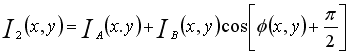
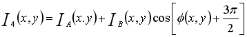
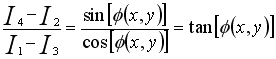
Top of Page The polarization states at the 4 cameras, 4, 5, 6, and 7, are given by positions 10, 12, 9, and 13, respectively. The relative phase shifts between these polarizations are 0o, 90o (π/2), 180o (π), and 270o (3π/2), respectively. We will call the intensities at these cameras I1, I2, I3, and I4. These intensities can be written as,1
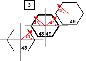
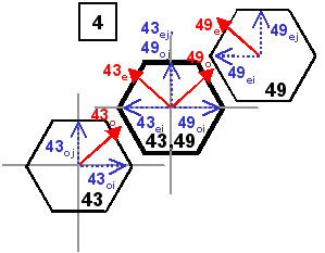
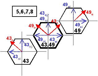
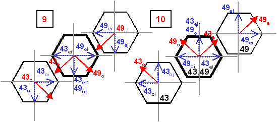
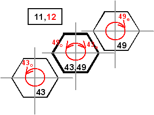
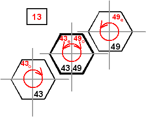
where A and B represent images from mirror segment A and segment B (#43 and #49 above), the two images that are interfering with each other, and
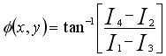
These equations can then be solved to find  (x,y). Subtracting
the equations gives, (x,y). Subtracting
the equations gives,
Taking the ratio of these two equations gives an expression for evaluating (x,y),
So,
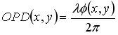
This phase difference, or wavefront error, between the two mirror segments is like a piston at each pixel. By calculating the phase error for every pixel in the image of the mirror segment, the wavefront can be mapped across the segment. The optical path difference can be calculated from the wavefront error as,
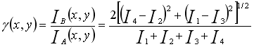
A contrast function can be calculated to determine the intensity modulation across the segment. This function,
A value near 1 is good contrast, a low value implies low contrast. This is one of the first checks in the CCAS program (after a comparison of the pixel to a minimum brightness value). If the pixel contrast is below a minimum value, 0.125, that pixel is thrown out. The phase function, (x,y), contains an arctangent, which
has discontinuities.
The only defined values for this function are between π/2
and
π/2.
This range can be extended to 0 to 2π by
looking at
the signs of the sine (I4-I2) and cosine (I1-I3)
functions in the arctan. Table 1 shows the corrections that should be made.
After these corrections,
there is still a discontinuity at every value of 2π.
This can be corrected by
adding multiples of 2π to (x,y) every
time a discontinuity is encountered to join the data into a smooth function.
This is called phase unwrapping.2Table 1
For the CCAS measurement, a maximum of 6 fringes can be resolved on a mirror segment. Each fringe corresponds to about 0.06 arcsec of tip or tilt. The camera resolution gives at least 2 pixels per fringe in this case. This means that phase variations between adjacent pixels cannot be more than π. If the phase difference calculated for two pixels is greater than π, then multiples of 2π must be added or subtracted to phase of the second pixel to meet this condition. Top of Page APPENDIX B Software Flowchart by Mike Ward
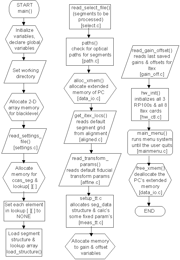
Software Flow Outline A separate manual is available from Mike Ward which documents each routine in the CCAS software. This appendix is merely an outline of the program flow generated by Wolf while debugging the physics in the code. At this point, the equations using the 4 camera intensities have been verified, except for a factor of 2 in the contrast equation. This could have been accounted for in selection of the minimum contrast value, but that is not known. The 2π ambiguity removal section and the plane fitting section are still being evaluated. Top of Page INITIAL SETUP STUFF: ccasv4.c main() load_structure () In rd_struc.c Loads in x,y positions for segments in the hex structure of the mirror array. read_select_file () In select.c Reads which segments are selected from the mirror selection file. Determines which is the reference segment. save_select_file () get_select_file_num () set_select_file_num () paths () In paths.c Run through the 91 segments and wipe out all parent-child relationships. Set the reference segments parent to be itself and its generation to 0. For each segment with a parent, see how many children it has by looking +/- 1 in each shearing direction and checking all 4 surrounding segments. Increment generations along the way. setup_child (n, nchild, &nchildren) In paths.c If not a valid segment, return. If child is not selected, return. If the child has no parent, set up as first parent. If the child has one parent, see if this is a second parent. Put parent index into childs structure. alloc_xmem () In data_io.c Allocates computer memory. get_itex_locs () In aligngrid.c Reads itex grid locations from disk at startup. read_transform_params () In affine.c ( which transformation functions for fiducial registration) Reads a file with transform parameters for all 8 buckets. setup_tt () In
meas_tt.c Sets up the i,j pixel mask based on segment heights and widths. Converts distances to arcseconds. Counts up the number of pixels in the mask. read_gain_offset (TIP_TILT) read_gain_offset (PISTON) hw_init () In hw_ctl.c Sets up serial communications, com2. main_menu () In mainmenu.c Gives keyboard selections on the main menu. free_xmem () In data_io.c Frees up all the memory used for images. TIP/TILT MEASUREMENT (t on main menu): tip_tilt_menu () In tt_menu.c tip_tilt_settings () In tt_menu.c Turns off laser diodes, fiducial diodes, opens HeNe shutter, sets shutter speed field_mode () In hw_ctl.c frame_mode_flag = FALSE continuous_video () In itexutil.c send_rp100_all () In hw_ctl.c show_tip_tilt_menu () In tt_menu.c Displays keyboard options on the Tip/Tilt menu. SNAP FRAMES (enter on tip/tilt menu): capture_mode () In itexutil.c load_capture_luts () In itexutil.c Set RGB stuff. snap_all () In itexutil.c freeze_video () In hw_ctl.c send_rp100_1 () In itexutil.c all_video_2_xmsdata () In data_io.c Download frames for all buckets and arms. BEGIN PROCESSING (b on tip/tilt menu): auto_power_flag = TRUE tip_tilt () In show_tt.c power = measure_all_tip_tilts () In meas_tt.c Run through all the segments, sets warnings to 0 Run through each arm view_image (arm, 0, FALSE) graphics_mode () capture_mode () load_graphics_luts () Run through each segment Get each segment number, arm, contrast value If no errors or warnings set, draw a green circle on this segment If there are errors, draw a red circle on this segment measure_tip_tilt (&dx, &dy, arm, segnum) get_seg_data (TIP_TILT, arm, segnum) The segdata structure is loaded with the data for the specified arm and cameras segdata[bucket][i][j] * gain[mode][arm][bucket] + offset[mode][arm][bucket] blacklevel[mode][arm] get_piston () Create a segment pixel mask by stepping through y[i], x[j] within the segment height and width bounds ok [i] [j] = mask [i] [j], where mask [i] [j] = x[j]2 * y[i]2 <= seg_radius2 Step through this mask, for each pixel: Sum the pixel on each camera If > than MIN_BRIGHTNESS * 4, go on If contrast is > MIN_CONTRAST, calculate piston for the pixel C = [2 {(I0-I2)2 + (I3-I1)2}]1/2 / (I0+I1+I2+I3) piston = arctan [(I3-I1) / (I0-I2)] If lower than min brightness or contrast, make that pixel and the surrounding 6 pixels FALSE in ok [i] [j] mask If 50% of pixels in the segment are FALSE, return BAD piston If piston is BAD, set fringe warning for this segment If the other segment associated with fringes on the bad one is downstream (a later generation) of the bad one, set fringe warnings for it too Set segment[segnum].axis_rel[arm].contrast = VOID Send messages to screen warning this segment is bad Set segment[segnum].axis_rel[arm].xtilt = 0 Set segment[segnum].axis_rel[arm].ytilt = 0 These are the x&y tilts eventually sent to the mirror correction file. This sets the unmeasurable ones to zero. resolve_2pi () Step through each y[i], x[j] pixel in the segment If [i],[j] is ok, check [i],[j-1] (the one to the left) If [i],[j-1] ok, valx = piston[i][j] - piston[i][j-1] If valx > p, sumdx = sumdx +valx-2p
If valx < -p, sumdx = sumdx +
valx+2p Else, sumdx = sumdx + valx Count number of dxs = ndx Check the above pixel If [i-1][j] ok, valy = piston[i][j] piston[i-1][j] If valy > p, sumdy = sumdy + valy - p
If valy < -p, sumdy = sumdy +
valy + p Else, sumdy = sumdy + valy Count number of dys = ndy dx_approx = sumdx / (ASPECT_RATIO * ndx) dy_approx = sumdy / (2 * ndy) Step through each y[i], x[j] pixel in segment If [i], [j] is ok, intercept[i][j] = piston[i][j] x[j] * dx_approx y[i] * dy_approx Stuff I
dont understand
If all pixels ok, do sym_plane_fit (dx,dy) (uses symmetry) If not, do plane_fit (dx,dy) plane_fit () This does a least squares fit to the piston values for the segment, to get x&y tilts for it. where x = x[j], y = y[i], z = piston[i][j] denom = -(Sx2*Sy2*n) + (Sx2*{Sy}2) + (n*{Sxy}2) 2*(Sxy*Sx*Sy) + ({Sx}2*Sy2) *dx = [ -(Sxz*Sy2*n) + (Sxz*{Sy}2) + (Syz*Sxy*n) (Syz*Sx*Sy) (Sz*Sxy*Sy) + (Sz*Sx*Sy2) ] / denom *dy = [ (Sxz*Sxy*n) (Sxz*Sx*Sy) (Syz*Sx2*n) + (Syz*{Sx}2) + (Sz*Sx2*Sy) (Sz*Sxy*Sx) ] / denom *dx = dx * convert_to_seconds[arm] *dy = dy * convert_to_seconds[arm] Convert dx & dy to arcseconds Assign dx to xtilt, dy to ytilt segment[segnum].axis_rel[arm].xtilt = *dx segment[segnum].axis_rel[arm].ytilt = *dy These get sent to the mirror correction file along with the zero values for bad segments.
accumulate_tt () In show_tt.c Set segment[segnum].axis_rel[arm].xtilt = 0 Set segment[segnum].axis_rel[arm].ytilt = 0 Run through each generation Run through the number of childern (nchild < N_SEGMENTS) If the segment falls into the current generation, show_tt () Display tip/tilt results on screen
1Gressler, William, HET Technical Report #78, HET Center of Curvature Alignment Sensor
(CCAS) Reference Document, 23 February 1995. |
Created: see
report date above Send comments to: webmaster@het.as.utexas.edu |